🌟 Love this site? Help keep it running 👉
Support Us✖
24 LED Larson Scanner
HuwR
Forum Administrator
• 1 Comments
Introduction
The Larson Scanner is one of those timeless electronics projects — the hypnotic red sweep made famous by the Cylons in Battlestar Galactica and KITT in Knight Rider. Both were created by Glen A. Larson, and both inspired generations of makers to recreate that iconic effect.
This build brings the classic scanner into the Raspberry Pi era using a custom PCB, 24 LEDs, and a dash of Charlieplexing magic.
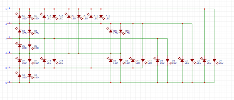
Instead of dedicating one GPIO pin per LED, we’ll use Charlieplexing, a clever wiring technique that allows control of n2−n LEDs with only n pins. With 6 GPIO pins, we can drive up to 30 LEDs — more than enough for our 24‑LED scanner.
Hardware Overview
PCB Layout
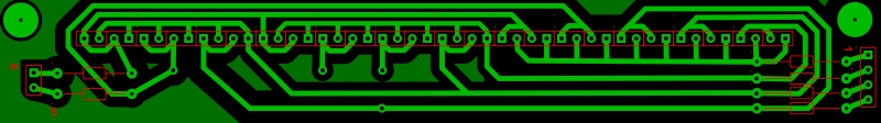
The board was designed in Sprint‑Layout and arranges all 24 LEDs in a clean, straight line for that unmistakable scanner look
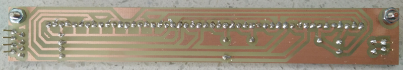
Fabrication
The PCB was etched and soldered by hand. Because Charlieplexing relies on precise pin‑to‑pin relationships, careful soldering is essential
Charlieplexing Setup
Charlieplexing lets you control up to n2−n LEDs using only n GPIO pins. With 6 pins, the Pi can theoretically drive 30 LEDs — plenty for this project’s 24‑LED array.
Pins used: GPIO 13, 16, 19, 20, 21, 26
Each LED is defined by a pair of pins: one set HIGH, one set LOW, and the rest left as inputs.
Software Implementation
The scanner is driven by a Python script using the RPi.GPIO library.
sudo apt-get update
sudo apt-get install rpi.gpio
Key Concepts
Pin Resetting: Before lighting each LED, all pins are set to input mode to prevent ghosting.
Lighting an LED: One pin goes HIGH, another LOW, the rest stay as inputs.
Sweep Effect: LEDs are lit in sequence, then reversed, creating the classic back‑and‑forth motion.
Core Script
The page includes the full Python script that:
Builds the Charlieplex LED matrix
Defines the sweep order
Supports an optional repeat count via -l
Monitors GPIO pin 5 for an external stop signal
Cleans up GPIO state on exit
import sys, getopt
# Import the module that runs the GPIO pins
import RPi.GPIO as gpio
# Import the sleep function for pausing
from time import sleep
# set the GPIO pins to BOARD mode
gpio.setmode(gpio.BCM)
#If an argument is passed then set the repeat counter
repeatcount=0
myopts, args = getopt.getopt(sys.argv[1:],"l:")
for o, a in myopts:
    if o == '-l':
        repeatcount=int(a)
# This function lights a specific LED. The led variable input is a 2 item
# list, each item representing a pin
def lightLED(led):
#First clear the pins, by setting them all to input
    for pin in charliePins:
        gpio.setup(pin,gpio.IN)
#Now set up the first pin for HIGH OUTPUT
    gpio.setup(led[0],gpio.OUT)
    gpio.output(led[0],gpio.HIGH)
#Now set up the second pin for LOW OUTPUT
    gpio.setup(led[1],gpio.OUT)
    gpio.output(led[1],gpio.LOW)
# Define the array of pins used as leads
charliePins=[13,16,19,20,21,26]
# Define the order for triggering the LEDs
charlieOrder=[1,0,3,2,5,4,7,6,9,8,11,10,13,12,15,14,17,16,19,18,21,20,23,22]
# Build the array of LEDs by cycling through the pins and creating the pairs.
# It has the disadvantage of not making them in order for larger sets of
# pairs, but is easier to maintain, IMO.
charlieLEDS=[]
for i in range(0,len(charliePins)-1):
    for j in range(i+1,len(charliePins)):
        charlieLEDS.append([charliePins[i],charliePins[j]])
        charlieLEDS.append([charliePins[j],charliePins[i]])
#Run the code over and over and over again
try:
    counter = 0
    while 1:
        if repeatcount > 0:
            counter=counter+1
        for led in charlieOrder:
            lightLED(charlieLEDS[led])
            sleep(.042)
        if repeatcount > 0:
            counter=counter+1
        for led in reversed(charlieOrder):
            lightLED(charlieLEDS[led])
            sleep(.042)
        if counter > repeatcount-1:
            if repeatcount>0:
                raise ValueError('limit reached')
#check pin 5 to see if we need to quit
#pin 5 can be set high by another script to trigger the scanner to stop.gpio.setwarnings(False)
        gpio.setup(5,gpio.IN)
        if gpio.input(5):
            quit()
except KeyboardInterrupt:
        print 'interrupted'
except ValueError as err:
        print(err.args)
finally:
        gpio.cleanup()
Advanced Features
Automatic Stop: A separate script can set GPIO pin 5 HIGH to stop the scanner after the next sweep.
Repeat Count: Use -l to limit the number of sweeps.
Safety: Always use resistors to protect your LEDs from overcurrent.
import RPi.GPIO as gpio
gpio.setwarnings(False)
gpio.setmode(gpio.BCM)
gpio.setup(5,gpio.OUT)
gpio.output(5,gpio.HIGH)
Final Build
The finished scanner runs on a Raspberry Pi Zero 2 W and produces a smooth, glowing red sweep across all 24 LEDs. The project is housed in a custom 3D‑printed case designed specifically for this build.
A perfect blend of retro sci‑fi charm, modern microcontrollers, and maker‑spirit.
Charlieplexing sounds like wizardry the first time you hear it — “control 24 LEDs with only 6 pins?!” — but the core idea is surprisingly simple once you see it.
Let’s break it down with visuals and plain language.
The Big Idea
If you have n microcontroller pins, you can control up to:
n2−n
LEDs.
With 6 pins, that’s:
62−6=30
So your 24‑LED Larson Scanner fits comfortably within that limit.
Why it works
LEDs are directional — electricity only flows one way.
Charlieplexing takes advantage of this by:
Setting one pin HIGH (positive)
Setting one pin LOW (negative)
Leaving all other pins as inputs (disconnected)
Only one LED is wired between those two pins in that direction, so only that LED lights.
Visualizing a Single LED
Imagine two GPIO pins:
Pin A ---->|---- Pin B
If A = HIGH and B = LOW, the LED lights.
If A = LOW and B = HIGH, nothing happens (the LED is reversed).
Now scale it up
With 3 pins, you can already control 6 LEDs:
Pin 1 ---->|---- Pin 2
Pin 2 ---->|---- Pin 1

Pin 1 ---->|---- Pin 3
Pin 3 ---->|---- Pin 1

Pin 2 ---->|---- Pin 3
Pin 3 ---->|---- Pin 2
Each arrow is a different LED.
This is the whole trick — every ordered pair of pins represents a unique LED.